Theory of TEM image formation at low voltages
Electron scattering has been applied as a conventional method for determining and imaging nanostructures since several decades. Modelling electron scattering is essential for understanding the scattering process taking place during experiments, and to interpret the contrast of high-resolution transmission electron microscopy (TEM) images. In case of high-energy electron waves (>100 keV) propagating through atomically thin specimens, the scattered electron wave can be described as a simple product of the incident electron wave and an object transmission function. This so-called phase-object approximation (POA) completely neglects dynamical effects, inelastic scattering, and backscattering [1].
For elastic scattering within thick samples, dynamical effects become important, i.e., electrons are scattered several times resulting in complicated interference patterns in the image. Multiple elastic scattering within a thick sample is usually simulated by employing either the Bloch-wave formalism [2] or the multislice algorithm [3]. In the latter method, the sample is sliced into thin layers and the static sample potential in each slice is projected along the optical axis onto a plane. The propagation of the incident electron wave through each of these planes is modelled by the POA, while the propagation between adjacent slices is described by the Fresnel propagator of vacuum.
For electrons accelerated by low voltages like 20 kV, the interaction between beam and target electrons becomes so strong that inelastic scattering needs to be taken into account [4]. In this case, energy is transferred from the scattering electron to the target, which gets excited from its initial ground state. This entangles the electron with the target, i.e., in contrast to elastic scattering, the outgoing electron can be no longer described by a single wave function. Instead, one has to consider many partial waves, which are only coherent if they belong to the same excited object state. Equivalently, one can employ the concept of the density matrix, or mutual coherence function (MCF), to describe the partial coherence of inelastic scattered electrons [5-8].
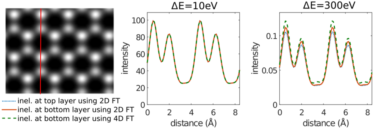
The image calculation involving inelastic scattering involves multiple 4D Fourier transforms, which is computationally expensive. In our group, we employ the method of matrix diagonalization to convert 4D Fourier transforms to 2D Fourier transforms [9]. In this way, the computational efficiency is improved, which allows us to study more complicated scattering problems.
[1] R. Glauber, High energy collision theory, Lectures in theoretical physics 1 (S 315).
[2] A. Howie, Proceedings of the Royal Society of London A: Mathematical, Physical
and Engineering Sciences, 271 (1963) 268-287.
[3] J. M. Cowley, A. F. Moodie, Acta Crystallographica 10 (10) (1957) 609-619.
[4] H. Rose, Optik 45 (1976) 139-158.
[5] H. Rose, Ultramicroscopy 15 (1984) 173-191.
[6] H. Kohl, H. Rose, Adv. Electron. Electron Phys. 65 (1985) 173-227.
[7] S. L. Dudarev, L. M. Peng, M. J. Whelan, Phys. Rev. B 48 (18) (1993) 13408-13429.
[8] P. Schattschneider, Phys. Rev. B 59 (1999) 10959-10969.
[9] Z. Lee, R. Hambach, U. Kaiser and H. Rose, Ultramicroscopy 175 (2017) 58-66.